AllSky7 Sensor Board Manual (Rev 1.1)
Components
The sensor board consists of the following hardware components:
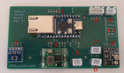
- Raspberry Pi Pico RP2040-ETH micro-controller with CH9120 Ethernet chip and USB-C port
- Internal temperature and humidity sensor
- buck converter 12V -> 5V
- GPS receiver
Note: The GPS antenna must be attached the the receiver and mounted horizontally inside the dome with the sensor point on top. The sensor support different signals like GPS (USA), BEIDOU (China), GALILEO (EU), GLONASS (Russia) and QZSS (Japan) - 12V power in
- 12V power out
- 5V power out
- Connector for external temperature and humidity sensor
- 3.3V power out
- relay add-on (optional)
Purpose
The purpose of the device is to determine certain parameters from inside and outside the AllSky7 cameras:
- GPS position
- 1PPS time signal
- temperature and humidity inside the dome
- temperature and humidity outside the dome
In addition, the device provides different voltages and digital ports for further sensors. An optional relay can control additional hardware like heaters, coolers or fans based on the climate conditions inside and outside the dome. Note that the power consumption for heaters and coolers is too large to be provided by the camera itself. So you need to provide a separate power supply.
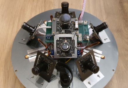
Mounting
The device is mounted below the zenith cameras. It is powered by 12V, and connected via an Ethernet cable to the Ethernet switch inside the camera dome.Attention! Never attach the internal power supply and USB-C port at the same time. This will damage sensors and the microcontroller.
Interface
The device has a static IP address 192.168.76.70. Communication is conducted via HTTP and can be initiated via curl, as in the following examples.- curl http://192.168.76.70/get_help - returns a help text with available services
- curl http://192.168.76.70/get_version - returns the firmware and configuration file version
- curl http://192.168.76.70/get_sensor - returns current sensor data in JSON format
- curl http://192.168.76.70/get_location - returns average geo-location data in JSON format
- curl http://192.168.76.70/set_pin?sqm=x - sets pin for SQM sensor. Default is 6
- curl http://192.168.76.70/set_debug?device=< usb | ether | file > - configure that log output is written to the serial port (USB), the Ethernet port or a local debug file
Note: You can listen to the debug output on ethernet with curl --ignore-content-length http://192.168.76.70/ - curl http://192.168.76.70/set_debug?level=< none | ether | noether | gps | nogps | sensor | nosensor | relay | norelay | config | noconfig | pps | nopps | flash | noflash | log | nolog | all > - activates or deactivates certain debug information
Note: You can add further debug information by calling the service multiple times, and deativate all debugging with level=none - curl [-o filename] http://192.168.76.70/get_log?type=< sensor | debug > - returns the sensor logfile in CSV or the debug logfile in TXT format and stores it optionally with the given filename
Note: The HTML header will contain a CRC32 value of the file. Pls. check the value before you purge the logfile - curl http://192.168.76.70/purge_log?type=< sensor | debug > - purges the sensor or debug logfile
- curl http://192.168.76.70/purge_log?date=yyyy/mm/dd - purges entries from the sensor logfile older than a given date
- curl http://192.168.76.70/format_fs - formats the LitteFS filesystem
Note: This will delete the configuration file and all logfiles - curl http://192.168.76.70/do_reset - resets the sensor board
- curl --data-binary @image.bin -H /"FileSize: xxxxxx/" -H /"CRC: xxxxxxxx/" http://192.168.76.70/put_firmware -
uploads a firmware file named image.bin
Note: CRC is the CRC32 value of the file, and Filesize the length of the file. Both parameters are mandatory and will be checked by the device - curl http://192.168.76.70/do_update - executes the update to a new firmware version which was uploaded before
- curl --data-binary @config.csv -H /"CRC: xxxxxxxx/" http://192.168.76.70/put_config - uploads a configuration file named config.csv
Note: CRC (optional) is the CRC32 value of the file, and FileSize (mandatory) the length of the file. Both parameters will be checked, if available.
The configuration file version must match to the firmware version.
Configuration File
You can configure the device by uploading a configuration file.
Here is a sample configuration file.
# configuration file for AllSky7 Sensor Board
version,1.1
temp,0,5
hum,90,70
indewpoint,3,10
sensor,dp
led,on
sensorlog,5
debugdevice,usb
debuglevel,all
debuglevel,nogps
Everthing behind a hash sign (#) is regarded as remark and omitted. The following parameters can be configured:
- version: Configuration file version. This is the only mandatory parameter and it must be in the first line of the configuration file, which is not a comment line. The file version must match to the file version supported by the device firmware.
- temp - temperature at which the relay is to be switched on and off
- hum - humidity at which the relay is to be switched on and off
- indewpoint - difference between outside temperate and dewpoint inside the dome at which the relay is to be switched on and off
- sensor - which sensor shall trigger the relay: inside (in) or outside (out) the dome, or dew point (dp)
- led - shall the LED display the sensor board status (on) or shall it remain dark (off)
- sensorlog - frequency at which sensor log data are written (in min)
- debugdevice - to which device shall debug log data be written: serial port (usb), ethernet port (ether) or local debug file (file)
- debuglevel - which debug information shall be written: none, ether, gps, sensor, relay, config, pps, flash, log, all
Note: this line can be given multiple times in the config file
When you install a heating device, the temperature for switching the relay on should be lower than the switch off temperature, or the humiditidy for switching it on should be higher than the switch off humidity. In case of a cooling device of fan, the values should be vice versa.
Sensor Data
Here is a typical JSON record which is returned from a get_sensor HTTP request:
{
"firmwareversion":"1.56",
"firmwaredate":"2025/07/28",
"hardwaretype":"Waveshare RP2040-ETH",
"insensortype":"HTU31D",
"outsensortype":"HTU31D",
"utcdate":"2025/09/13",
"utctime":"22:54:54.738",
"intemperature":"40.5",
"inhumidity":"28.9",
"indewpoint":"18.9",
"outtemperature":"23.5",
"outhumidity":"48.0",
"outdewpoint":"11.8",
"pm2.5":"9,7.",
"pm10":"7.5",
"sqm":"18.6",
"longitude":"11.12345",
"latitude":"49.12345",
"altitude":"500",
"direction":"295",
"velocity":"0.0",
"satellites":"13",
"hdop":"0.9",
"accuracy":"high",
"relaystate":"off"
}
Most of the attributes are self-explanatory. insensortype and outsensortype are the type of temperature and humidity sensor installed inside and outside the camera. pm2.5, pm10 and sqm are air and sky quality parameters which are populated if the corresponding sensors are installed. direction and velocity are measures from the GPS sensor in case the camera is moving. utcdate and utctime are the time when the get_sensor HTTP request was received by the decide, accurate to ~1ms. satellites are the number of satellites used for the GPS solution and hdop the horizontal dilution of precision, a measure of the quality of the signal. accuracy translates the hdop value to low, medium or high accuracy.
Monitoring and Logging
The micro-controller has 2MB of flash memory, half of which is used for the internal LittleFS file system.
All sensor data will be written in regular, defined intervals to a local logfile. Note that only 1 MB of flash data is available. If every minute a log entry is written, the filesystem will be full in about 4 days. In order not to loose sensor data, you should regularly download the logfile, and purge it thereafter. This is typically be achieve with the get_sensor_log.py facility - see below.
You can use the sensor data logfile to display the sensor value change over time and determine critical values, e.g. when the dome is fogging from the inside.
For debug purposes you can write certain device logdata into a local logfile, or to the Serial or Ethernet port.
Note that sending debug outpout to the ethernet port will interfer with the output of other HTTP requests.
Depending of the status of the device, the LED on the micro-controller shows the following colors:
- green - all sensors detected, filesystem accessible, relay if off
- blue - relay is on
- yellow - some sensor data could (not yet) be retrieved
Note: It may take some minutes until the GPS position is available - red - at least one temperature and humidity sensor is not responding
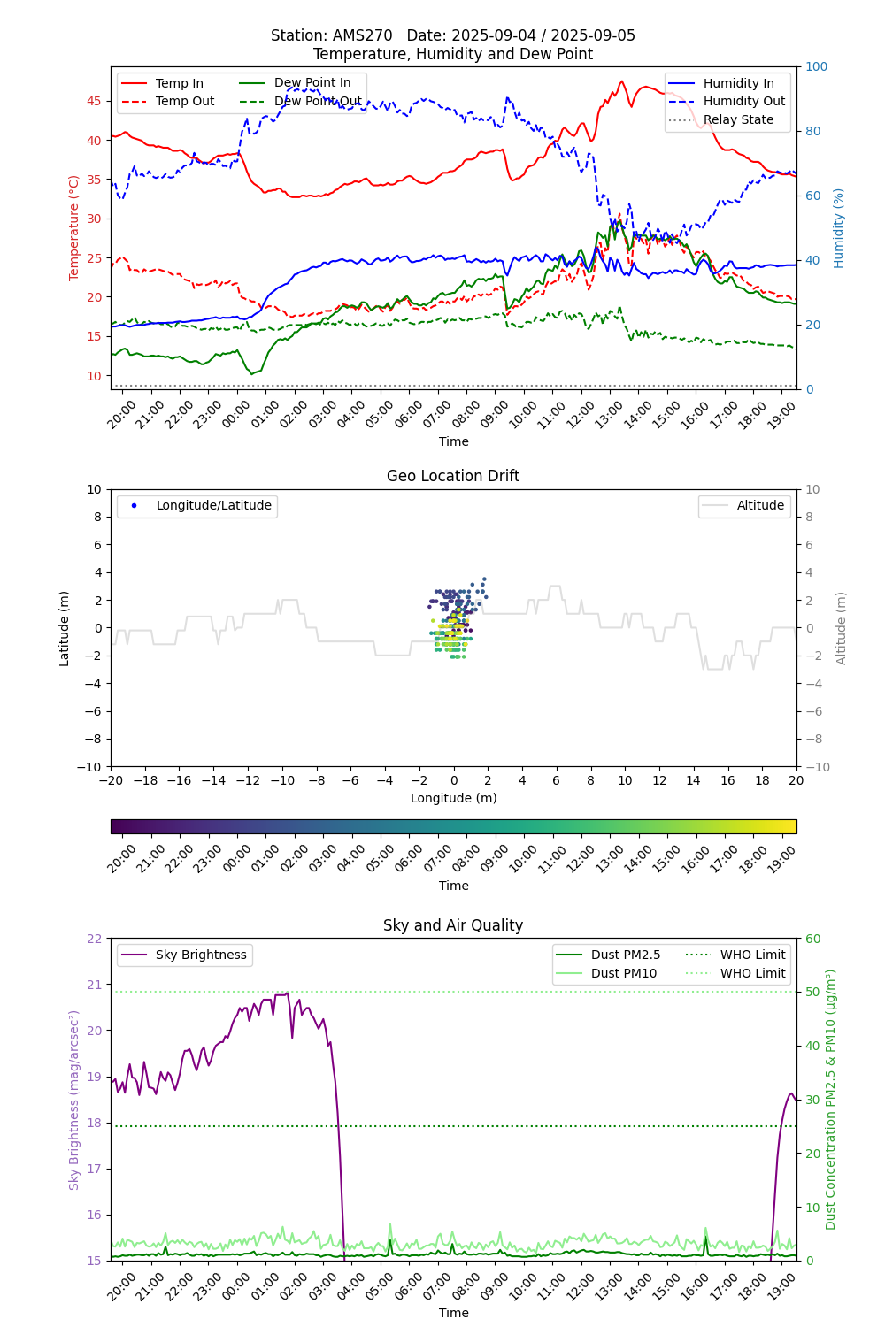
Visualization
The tool get_sensor_log.py located in the ~/amscams/sensor folder is meant to retrieve log data from the sensor board, purge them regularly, and create a visual presentation of the data. The script should be configured in cron and executed every 5 mins.
The latest graph can be accessed via http://archive.allsky.tv/AMSxxx/sensor/latest.png and the history via http://archive.allsky.tv/AMSxxx/sensor/data.html.
Here is an example.
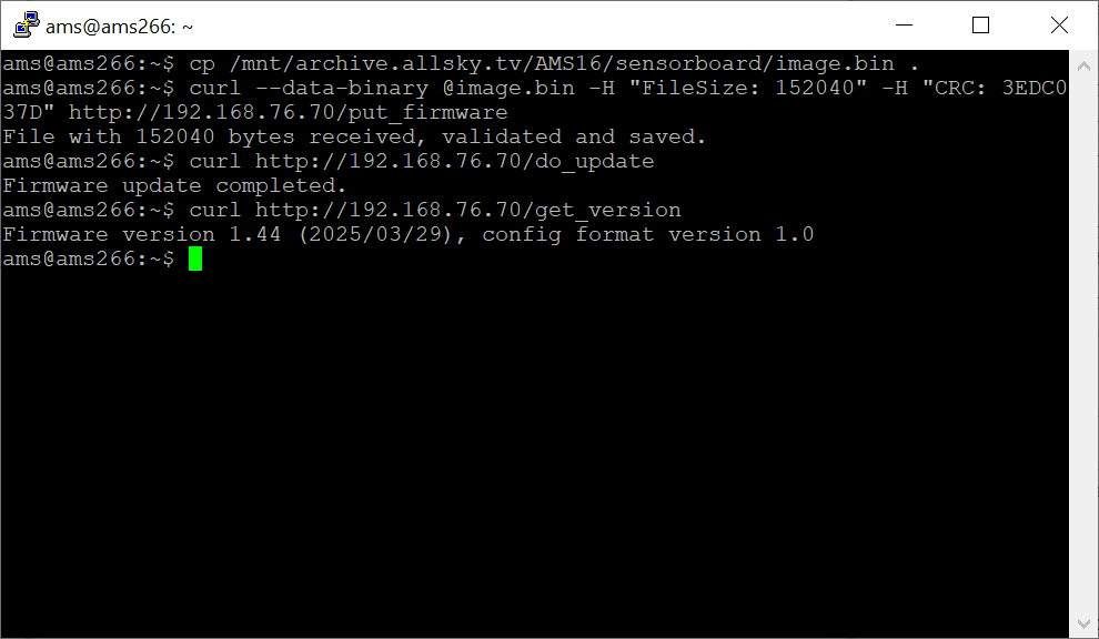
Firmware Upgrade
To upgrade the firmware, upload the new firmware file together with the file size and CRC32 fingerprint to the device with the corresponding HTTP command.
If the upload was successful, you can execute the update, which takes less than a second, via the next command.
If there are breaking changes in the format of the configuration file, you should format the filesystem beforehand.
The next image shows typical steps of a firware upgrade.
Alternatively, you can connect the device via USB-C port and upload the new firmware via the file explorer.
Attention! Never attach the internal power supply and USB at the same time. This will damage sensors and the microcontroller.
Optional Sensors
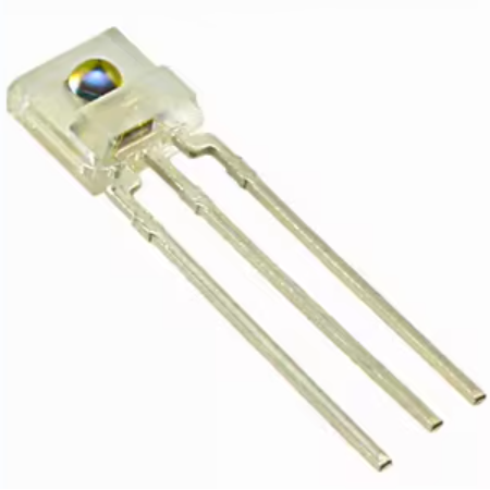
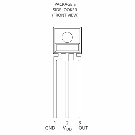
Two additional sensor types are currently supported by the sensor board.TSL237 is a tiny brightness sensor that allows to measure the night sky quality (SQM), i.e. the sky brightness in mag/arcsec2 (in the range of about 8..22 mag/arcsec2). Pin1 (GND) and pin2 (VDD) are to be connected with the 3.3V power out connector of the sensor board, pin3 (OUT) with pin6 of the microcontroller. If you select a different pin, you have to configure it in the configuration file.
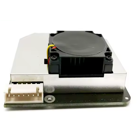
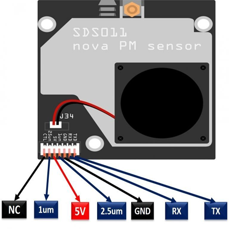
SDS011 is an air quality sensor which measures the concentration of dust particles up to 2.5 micron (pm2.5) and 10 micron (pm10). Pin3 (GND) and pin5 (5V) are to be connected with the 5V power out connector of the sensor board, pin1 (TX) and pin2 (RX) with pin8 and pin9 of the microcontroller.
Known Issues
Due to a problem with the provided Ethernet library, the HTTP data gets often corrupted during the transfer. This results in malformed requests or incomplete uploads and downloads.
If your HTTP service request returns an error message, or if the CRC of the file upload is incorrect, just repeat the HTTP call until it is successful.
Note: This problem occurs less frequentl when runnung Ubuntu 22.04 or newer.
If you download logdata, calculate the CRC32 value of the file (e.g. with 7-ZIP: 7z.exe h < filename >) and compare it with the CRC value given in the return header.
Alternatively, if you upload a configuration file and want to make sure it is not getting corruped, add the CRC32 values to the HTML header.
If it is not matching, try the download again.